Trailer towing
Introduction
Section titled “Introduction”This chapter contains information on the following subjects:
- Technical requirements
- Fitting the detachable ball head
- Removing the ball head
- Hitching up and connecting a trailer
- Loading the trailer
- Driving with a trailer
- Retrofitting a towing bracket
- Maximum permissible trailer weight
- Maximum permissible gross train weight
Observe the national regulations on towing a trailer and using a towing bracket.
The vehicle is primarily designed to carry people and, with the appropriate technical equipment, can be used to tow a trailer. This additional load affects the service life of the vehicle, its fuel consumption and its performance, and under certain conditions can shorten the service intervals.
Towing a trailer not only increases the load on the vehicle, it also demands greater concentration from the driver.
In winter conditions, fit winter tyres to the wheels of the vehicle and the trailer.
Drawbar load
Section titled “Drawbar load”The maximum permissible nose weight on the ball head of the towing bracket must not exceed 50 kg.
Vehicles with start/stop system
Section titled “Vehicles with start/stop system”With a factory-fitted towing bracket, and with towing brackets fitted by Volkswagen, the start/stop system is deactivated automatically as soon as a trailer is connected.
If the trailer cannot be detected, or with towing brackets that were not retrofitted by Volkswagen, the start/stop system must be switched off manually before setting off, using the button in the upper part of the centre console. The start/stop system must remain switched off for the whole time the trailer is being towed ⇒ .
Additional information and warnings
Section titled “Additional information and warnings”- Exterior views
- Central locking system
- Lights
- Environmentally friendly driving
- Pull-away assist systems (start/stop system)
- Wheels and tyres
- Accessories, parts replacement, repairs and modifications
Always switch off the anti-theft alarm system before connecting or disconnecting a trailer ⇒ Anti-theft alarm system. The tow-away sensor could otherwise trigger the alarm unexpectedly.
Do not tow a trailer during the first 1,000 km with a new engine ⇒ Accessories, parts replacement, repairs and modifications.
Volkswagen recommends removing the ball head before driving without a trailer. In a rear-end collision, the damage to the vehicle can be considerably greater with the ball head fitted than without it.
In some model versions, the towing bracket is needed for towing other vehicles. The removed ball head should therefore always be carried in the vehicle.
Technical requirements
Section titled “Technical requirements”First read and observe the introductory information and safety warnings .
If the vehicle was fitted with a towing bracket at the factory, everything technically and legally necessary for towing a trailer has already been taken into account.
Only use a towing bracket that is approved for the permissible gross weight of the trailer to be towed. The towing bracket must be suitable for the vehicle and the trailer and must be securely attached to the underbody of the vehicle. Use a towing bracket with a detachable ball head. Always check and observe the information provided by the towing bracket manufacturer. Never fit a “weight-distributing” or “load-equalising” towing bracket.
Towing brackets fitted to the rear bumper
Section titled “Towing brackets fitted to the rear bumper”Never mount the towing bracket on the bumper or its mountings. The towing bracket must not impair the effectiveness of the bumper. Never modify the exhaust system or the braking system. Check at regular intervals that the towing bracket is securely attached.
Engine cooling system
Section titled “Engine cooling system”Towing a trailer places an increased load on the engine and the cooling system. The cooling system must contain sufficient coolant and be able to cope with the additional load of towing a trailer.
Trailer brake
Section titled “Trailer brake”If the trailer has its own braking system, observe the applicable regulations. The braking system of the trailer must never be connected to the braking system of the vehicle.
Emergency breakaway cable
Section titled “Emergency breakaway cable”Always attach a emergency breakaway cable between the vehicle and the trailer.
Rear trailer lights
Section titled “Rear trailer lights”The rear lights on the trailer must meet the legal requirements.
Never connect the trailer rear lights directly to the vehicle electrical system. If you are unsure about the correct electrical connection of the trailer, seek advice from a qualified workshop. Volkswagen recommends using a Volkswagen dealership for this purpose.
Exterior mirrors
Section titled “Exterior mirrors”If the traffic behind the trailer cannot be observed using the standard exterior mirrors of the towing vehicle, additional exterior mirrors are required, depending on the national regulations. The exterior mirrors must be adjusted before setting off and must provide an adequate field of vision.
Maximum power consumption of the trailer
Section titled “Maximum power consumption of the trailer”| Consumer | Europe, Asia, Africa, South and Central America | Australia |
|---|---|---|
| Brake lights, total | 84 W | 108 W |
| Turn signal, per side | 42 W | 54 W |
| Side lights, total | 100 W | 100 W |
| Rear lights, total | 42 W | 54 W |
| Rear fog light | 42 W | 54 W |
| The values given must not be exceeded. | ||
Because of the higher load on a vehicle that frequently tows a trailer, Volkswagen recommends having the vehicle serviced between the normal service intervals as well.
In some countries it is compulsory to carry an additional fire extinguisher in the vehicle if the gross weight of the trailer exceeds 2,500 kg.
Fitting the removable ball coupling
Section titled “Fitting the removable ball coupling”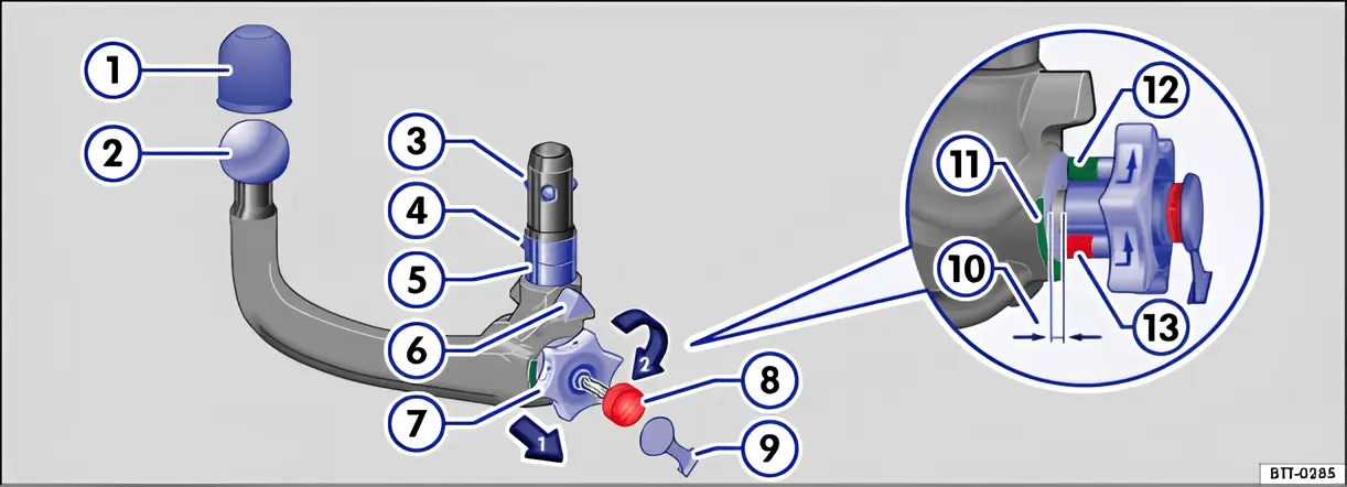
Fig. 92 Schematic representation: detachable ball head
First read and observe the introductory information and safety warnings .
The detachable ball head is located under the luggage compartment floor, next to the vehicle tool kit.
Key for fig. 92:
- Cover
- Ball
- Locking balls
- Locking ball release
- Shank
- Centring device
- Handwheel
- Keys
- Cover
- Gap (ball head tensioned)
- Green marking on the ball head
- Green marking on the handwheel
- Red marking on the handwheel
Step 1: Preparations
Section titled “Step 1: Preparations”- Before using the ball head for the first time, make a note of the number stamped on the key, so that a replacement key can be ordered if necessary.
- Remove the cover under the rear bumper by taking hold of it at the slot and pulling it downwards. Stow the cover in the vehicle.
- Take the plug out of the ball head mounting and stow it in the vehicle.
- Swing the trailer socket down on the right and then up to the left as far as it will go. This gives access to the ball head mounting.
- Check that the mounting, the handwheel 7, the shank 5 and the locking balls 3 of the ball head are clean and undamaged ⇒ . Clean them if necessary.
Step 2: Setting the ball coupling to the “ready” position
Section titled “Step 2: Setting the ball coupling to the “ready” position”The ball head can only be fitted correctly when it is tensioned.
- Hold the ball head in your left hand.
- Take the cover 9 off the lock and insert the key 8 into the lock.
- Turn the key clockwise.
- Using your right hand, pull the handwheel 7 out in the direction of the arrow until it engages. The ball head is now tensioned. The red marking 13 must now point to the green marking 11 on the ball head. The handwheel protrudes noticeably from the ball head. A gap of approximately 4 mm 10 is visible.
- Check that all the locking balls 3 can be pressed fully into the shank 5 of the ball head.
Step 3: Attaching the pre-tensioned ball coupling to the vehicle
Section titled “Step 3: Attaching the pre-tensioned ball coupling to the vehicle”Do not hold the handwheel of the tensioned ball head any longer. When it engages, the handwheel springs back into its previous position and can cause injuries ⇒ .
- Insert the tensioned ball head into the mounting tube from below.
- Push the ball head firmly upwards until it engages. Both centring devices 6 must locate in the mounting on the vehicle.
- The handwheel is now back in its previous position. There is no gap between the handwheel and the ball head.
- Turn the key 8 in the handwheel anti-clockwise and pull it out.
- The handwheel must no longer turn or be able to be pulled out.
- Put the cover 9 on the lock and stow the key in the vehicle tool kit.
Step 4: safety check
Section titled “Step 4: safety check”Check that the ball head has been fastened correctly:
- The green marking 12 on the handwheel points to the green marking 11 on the ball head.
- The handwheel must lie against the ball head with no gap.
- Shake the ball head firmly or pull it downwards. It must be firmly held in the mounting ⇒ .
- The lock must be locked and the key removed. The cover must also be covering the lock on the handwheel.
Removing the ball coupling
Section titled “Removing the ball coupling”First read and observe the introductory information and safety warnings .
- Uncouple the trailer ⇒ .
- Take the cover ⇒ fig. 92 9 off the lock on the handwheel.
- Insert the key 8 into the lock and turn it clockwise.
- Hold the ball head with your left hand ⇒ .
- Using your right hand, pull the handwheel 7 out in the direction of the arrow and hold it in this position.
- Turn the handwheel 7 in the direction of the arrow until it engages.
- Hold the handwheel in this position and pull the ball head down out of the mounting. The ball head is now tensioned.
- Release the handwheel and stow the tensioned ball head safely with the vehicle tool kit.
- Swing the trailer socket all the way from the left to the right, to prevent the mounting from becoming dirty or damaged.
- Insert the plug into the ball head mounting.
- Fit the cover in the bumper.
Hitching and connecting the trailer
Section titled “Hitching and connecting the trailer”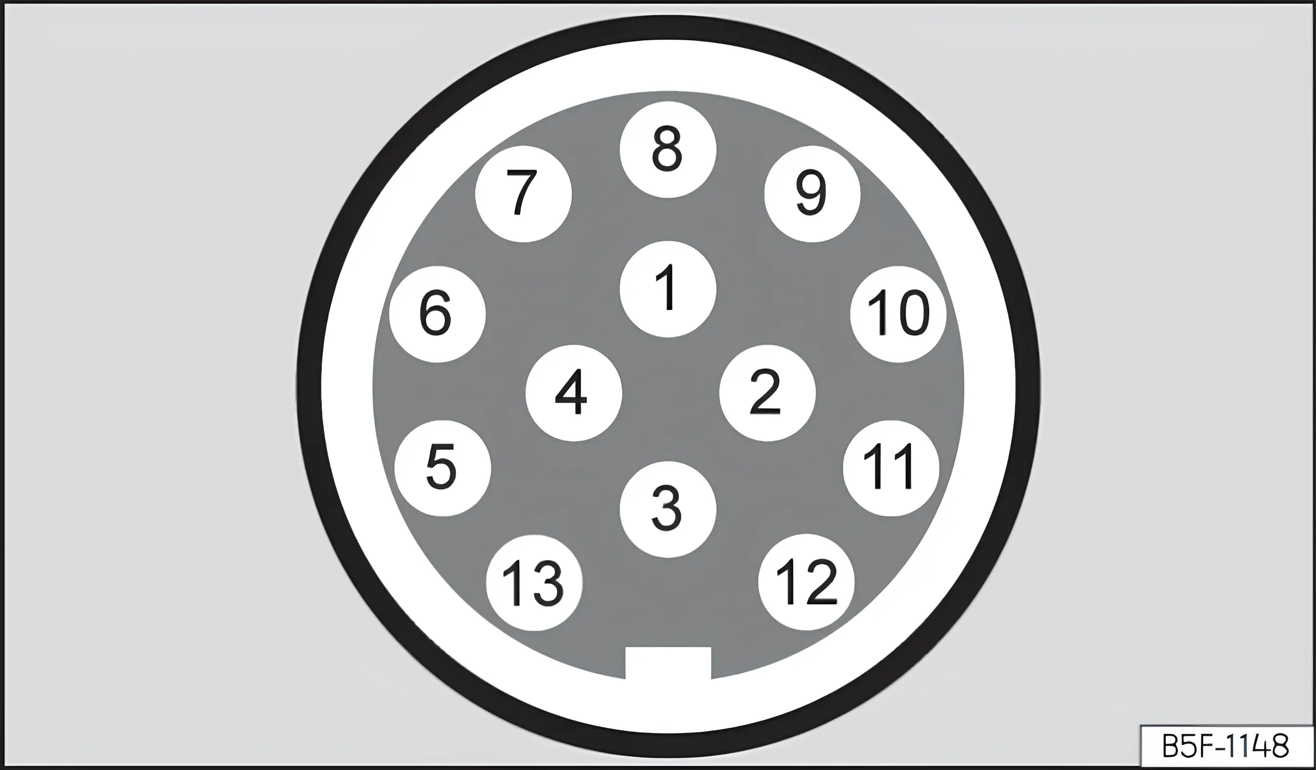
Fig. 93 Schematic representation: pin assignment of the trailer socket
First read and observe the introductory information and safety warnings .
Key for the schematic representation fig. 93:
| Pin | Meaning |
|---|---|
| 1 | Left turn signal |
| 2 | Rear fog light |
| 3 | Earth for pins 1-8 |
| 4 | Right turn signal |
| 5 | Right rear light |
| 6 | Brake light |
| 7 | Left rear light |
| 8 | Reversing light |
| 9 | Permanent positive |
| 10 | Charging lead positive |
| 11 | Not assigned |
| 12 | Not assigned |
| 13 | Earth for pins 9-13 |
Trailer socket
Section titled “Trailer socket”The electrical connection between the vehicle and the trailer is made through the 13-pin trailer socket. With the engine running, the electrical consumers in the trailer are supplied with voltage through the electrical connection (pin 9 and pin 10 of the trailer socket).
When the trailer is detected electrically, the consumers in the trailer are supplied with voltage through the electrical connections (pins 9 and 10). Pin 9 carries a permanent positive, so that the interior lighting of the trailer, for example, can be used. Electrical consumers such as the refrigerator in a caravan are supplied with voltage only while the engine is running (through pin 10).
The earth leads on pin 3 and pin 13 must not be connected to each other, to avoid overloading the electrical system.
If the trailer has a 7-pin plug, a suitable adapter lead must be used. The pin 10 function is then not available.
Emergency breakaway cable
Section titled “Emergency breakaway cable”Always attach the breakaway cable of the trailer to the vehicle correctly. Leave the breakaway cable slack enough to allow for cornering. However, it must not drag on the road surface while the vehicle is in motion.
Rear trailer lights
Section titled “Rear trailer lights”Ensure that the trailer rear lights work properly and comply with the legal requirements. Ensure that the maximum power consumption of the trailer is not exceeded ⇒ Maximum power consumption of the trailer.
Integration into the anti-theft alarm system
Section titled “Integration into the anti-theft alarm system”The trailer is integrated into the anti-theft alarm system under the following conditions:
- If the vehicle was fitted with an anti-theft alarm system and a towing bracket at the factory.
- If the trailer is connected electrically to the towing vehicle through the trailer socket.
- If the electrical systems of the vehicle and the trailer are working, fault-free and undamaged.
- If the vehicle is locked with the key and the anti-theft alarm system is active.
With the vehicle locked, the alarm is triggered as soon as the electrical connection to the trailer is interrupted.
Always switch off the anti-theft alarm system before connecting or disconnecting a trailer. The tow-away sensor could otherwise trigger the alarm unexpectedly.
Trailer with LED rear lights
Section titled “Trailer with LED rear lights”For technical reasons, a trailer with LED rear lights cannot be integrated into the anti-theft alarm system.
With the vehicle locked, the alarm is not triggered when the electrical connection to a trailer with LED rear lights is interrupted.
If there is a fault in the electrical system of the vehicle or the trailer, or in the anti-theft alarm system, have the equipment checked by a qualified workshop.
If an electrical device in the trailer is switched on and connected through the trailer socket while the engine is switched off, the vehicle battery will be discharged.
If the charge level of the vehicle battery is low, the electrical connection to the trailer is interrupted automatically.
Loading the trailer
Section titled “Loading the trailer”First read and observe the introductory information and safety warnings .
Trailer weight and nose weight
Section titled “Trailer weight and nose weight”The trailer weight is the weight that the vehicle can tow ⇒ . The nose weight is the weight exerted vertically from above on the ball head of the towing bracket ⇒ Maximum permissible trailer weight.
The trailer weight and nose weight given on the type plate of the towing bracket are only test values for the bracket. The values for the vehicle, which are often lower, are given in the vehicle registration documents. The data in the vehicle registration document takes precedence.
For driving safety, Volkswagen recommends always using the maximum permissible nose weight. Too low a nose weight has an adverse effect on the handling of the vehicle-trailer combination.
The nose weight increases the rear axle load and reduces the possible payload of the vehicle accordingly.
Gross train weight
Section titled “Gross train weight”The gross train weight is made up of the actual weight of the loaded vehicle and the weight of the loaded trailer.
Loading the trailer
Section titled “Loading the trailer”The vehicle-trailer combination should be balanced. To achieve this, use the maximum permissible nose weight and load the trailer at both the rear and the front:
- Distribute the load in the trailer so that heavy objects are as close as possible to, or above, the axle.
- Secure the load in the trailer properly.
Tyre pressures
Section titled “Tyre pressures”Adjust the tyre pressures for the trailer wheels in accordance with the trailer manufacturer’s recommendations.
Inflate the tyres of the towing vehicle to the maximum permissible tyre pressure ⇒ Wheels and tyres.
Driving with a trailer
Section titled “Driving with a trailer”First read and observe the introductory information and safety warnings .
Headlight setting
Section titled “Headlight setting”With a trailer connected, the front of the vehicle can rise and the dipped beam can dazzle other road users. Lower the headlight beam accordingly using the headlight range control. If the vehicle does not have a headlight range control, have the headlights adjusted by a qualified workshop. Vehicles with dynamic headlight range control adjust automatically and do not need to be set.
Special features when driving with a trailer
Section titled “Special features when driving with a trailer”- With a trailer that has an overrun brake, brake gently at first and then firmly. This avoids the jolting caused by the trailer wheels locking.
- Because of the gross train weight, the braking distance is longer.
- Select a lower range or a lower gear before descents, so that the engine also acts as a brake. The braking system could otherwise overheat and be damaged.
- The centre of gravity of the vehicle, and therefore its handling, changes as a result of the trailer load and the increased gross train weight.
- With an unladen towing vehicle and a loaded trailer, the centre of gravity is in a very unfavourable position. Drive particularly carefully and slowly in this combination.
Pulling away with a trailer on a hill
Section titled “Pulling away with a trailer on a hill”Depending on the gradient and the gross train weight, a parked vehicle-trailer combination can roll back slightly when pulling away.
Pull away on a hill with a trailer as follows:
- Press the brake pedal and hold it down.
- Apply the handbrake.
- With a manual gearbox: press the clutch pedal all the way down.
- Engage 1st gear or selector lever position D ⇒ Changing gear.
- Release the handbrake and, with the release button pressed, lower it carefully. At the same time, apply the accelerator gently and, with a manual gearbox, release the clutch pedal until you feel the vehicle beginning to move forwards. Read the information on the hill hold assist if necessary ⇒ Pull-away assist systems.
- Only release the handbrake lever once the engine has enough power to pull away.
- Pull away slowly.
Retrofitting a towing bracket
Section titled “Retrofitting a towing bracket”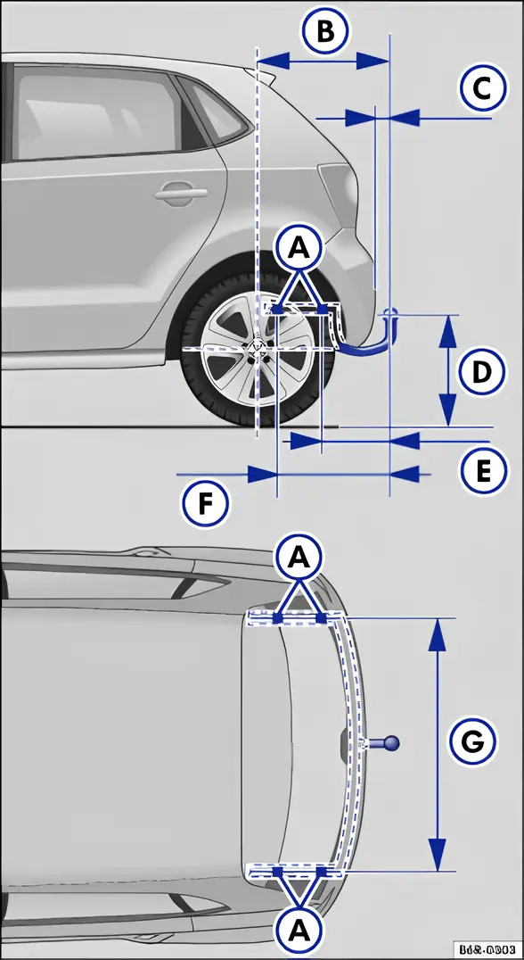
Fig. 94 Dimensions and attachment points for retrofitting a towing bracket
First read and observe the introductory information and safety warnings .
Volkswagen recommends having a towing bracket retrofitted by a qualified workshop. Modifications to the cooling system may be required, for example, or heat shields may have to be fitted. Volkswagen recommends using a Volkswagen dealership for this purpose.
The dimensions and distances must always be observed when retrofitting a towing bracket. The specified dimension from the centre of the ball to the road surface ⇒ fig. 94 D must not be exceeded. This also applies with the vehicle fully laden, including the maximum nose weight.
Dimensions ⇒ fig. 94:
- A Attachment points
- B 721 mm
- C at least 65 mm
- D 350-420 mm
- E 314 mm
- F 520 mm
- G 960 mm
Only use a towing bracket approved by Volkswagen for the relevant vehicle model.
Maximum permitted trailer weights
Section titled “Maximum permitted trailer weights”First read and observe the introductory information and safety warnings .
The data in the vehicle registration document takes precedence. All the data in this manual applies to the basic model. The type of engine fitted in the vehicle is given on the vehicle data sticker, in the service schedule or in the vehicle registration documents.
The values given may vary because of optional equipment, different model versions and special models.
Petrol engines
Section titled “Petrol engines”| Engine power | Engine code | Braked, gradients up to 12% | Braked, gradients up to 8% | Unbraked |
|---|---|---|---|---|
| 44 kW | CGPB | 800 kg | 1000 kg | 530 kg |
| 51 kW | CGPA | 800 kg | 1000 kg | 530 kg |
| 51 kW BlueMotion Technology | ||||
| 63 kW | CGGB | 1000 kg | 1200 kg | 5‑speed manual gearbox: 530 kg |
| 7‑speed DSG®: 550 kg | ||||
| 66 kW | CBZC | 1000 kg | 1200 kg | 5‑speed manual gearbox: 550 kg |
| 7‑speed DSG®: 560 kg | ||||
| 66 kW Bluemotion Technology | 550 kg | |||
| 77 kW | CBZB | 1200 kg | 1200 kg | 6‑speed manual gearbox: 540 kg |
| 7‑speed DSG®: 560 kg | ||||
| 77 kW BlueMotion Technology | 6‑speed manual gearbox: 550 kg | |||
| 7‑speed DSG®: 560 kg | ||||
| 103 kW | CPTA | 1200 kg | 1200 kg | 600 kg |
| 132 kW | CAVE | 1200 kg | 1200 kg | 630 kg |
| CTHE |
Petrol engines in the Cross Polo
Section titled “Petrol engines in the Cross Polo”| Engine power | Engine code | Braked, gradients up to 12% | Braked, gradients up to 8% | Unbraked |
|---|---|---|---|---|
| 51 kW | CGPA | 800 kg | 1000 kg | 560 kg |
| 63 kW | CGGB | 1000 kg | 1200 kg | 5‑speed manual gearbox: 560 kg |
| 7‑speed DSG®: 580 kg | ||||
| 66 kW | CBZC | 1000 kg | 1200 kg | 5‑speed manual gearbox: 570 kg |
| 7‑speed DSG®: 590 kg | ||||
| 77 kW | CBZB | 1200 kg | 1200 kg | 6‑speed manual gearbox: 570 kg |
| 7‑speed DSG®: 580 kg |
Diesel engines
Section titled “Diesel engines”| Engine power | Engine code | Braked, gradients up to 12% | Braked, gradients up to 8% | Unbraked |
|---|---|---|---|---|
| 55 kW without DPF | CFWA | 1000 kg | 1200 kg | 560 kg |
| 55 kW Bluemotion with DPF | 800 kg | 1000 kg | 570 kg | |
| 55 kW with DPF | CAYA | 1000 kg | 1200 kg | 570 - 610 kg |
| 66 kW with DPF | CAYB | 1200 kg | 1200 kg | 5‑speed manual gearbox: 570 kg |
| 7‑speed DSG®: 580 kg | ||||
| 66 kW Bluemotion Technology with DPF | 580 kg | |||
| 77 kW with DPF | CAYC | 1200 kg | 1200 kg | 580 kg |
Diesel engines in the Cross Polo
Section titled “Diesel engines in the Cross Polo”| Engine power | Engine code | Braked, gradients up to 12% | Braked, gradients up to 8% | Unbraked |
|---|---|---|---|---|
| 55 kW without DPF | CFWA | 1000 kg | 1200 kg | 600 kg |
| 66 kW with DPF | CAYB | 1200 kg | 1200 kg | 5‑speed manual gearbox: 610 kg |
| 7‑speed DSG®: 620 kg | ||||
| 77 kW with DPF | CAYC | 1200 kg | 1200 kg | 610 kg |
LPG engines
Section titled “LPG engines”| Engine power | Engine code | Braked, gradients up to 12% | Braked, gradients up to 8% | Unbraked |
|---|---|---|---|---|
| 63 kW | CMAA | 1000 kg | 1200 kg | 560 kg |
| 60 kW | CNKA | 1000 kg | 1200 kg | 560 kg |
Maximum permissible gross train weight
Section titled “Maximum permissible gross train weight”First read and observe the introductory information and safety warnings .
The data in the vehicle registration document takes precedence. All the data in this manual applies to the basic model. The type of engine fitted in the vehicle is given on the vehicle data sticker, in the service schedule or in the vehicle registration documents.
The values given may vary because of optional equipment, different model versions and special models.
The gross train weights given apply only up to an altitude of 1,000 m above sea level. For every further 1,000 m of altitude, the maximum permissible gross train weight must be reduced by 10%.
Petrol engines
Section titled “Petrol engines”| Engine power | Engine code | Gearbox type | Maximum permissible gross train weight ⇒ |
|---|---|---|---|
| 44 kW | CGPB | 5‑speed manual gearbox | 2385 kg |
| 51 kW | CGPA | 5‑speed manual gearbox | 2385 kg |
| 51 kW Bluemotion Technology | 2350 kg | ||
| 63 kW | CGGB | 5‑speed manual gearbox | 2585 kg |
| 7‑speed DSG® | 2615 kg | ||
| 66 kW | CBZC | 5‑speed manual gearbox | 2600 kg |
| 7‑speed DSG® | 2630 kg | ||
| 66 kW Bluemotion Technology | 5‑speed manual gearbox | 2580 kg | |
| 77 kW | CBZB | 6‑speed manual gearbox | 2795 kg |
| 7‑speed DSG® | 2835 kg | ||
| 77 kW Bluemotion Technology | 6‑speed manual gearbox | 2770 kg | |
| 7‑speed DSG® | 2800 kg | ||
| 103 kW | CPTA | 6‑speed manual gearbox | 2830 kg |
| 7‑speed DSG® | 2840 kg | ||
| 132 kW | CAVE | 7‑speed DSG® | 2890 kg |
| CTHE |
Petrol engines in the Cross Polo
Section titled “Petrol engines in the Cross Polo”| Engine power | Engine code | Gearbox type | Maximum permissible gross train weight ⇒ |
|---|---|---|---|
| 51 kW | CGPA | 5‑speed manual gearbox | 2370 kg |
| 63 kW | CGGB | 5‑speed manual gearbox | 2570 kg |
| 7‑speed DSG® | 2600 kg | ||
| 66 kW | CBZC | 5‑speed manual gearbox | 2600 kg |
| 7‑speed DSG® | 2630 kg | ||
| 77 kW | CBZB | 6‑speed manual gearbox | 2790 kg |
| 7‑speed DSG® | 2820 kg |
Diesel engines
Section titled “Diesel engines”| Engine power | Engine code | Gearbox type | Maximum permissible gross train weight ⇒ |
|---|---|---|---|
| 51 kW without DPF | CFWA | 5‑speed manual gearbox | 2630 kg |
| 63 kW Bluemotion with DPF | 2570 kg | ||
| 55 kW with DPF | CAYA | 5‑speed manual gearbox | 1270 - 2685 kg |
| 66 kW with DPF | CAYB | 5‑speed manual gearbox | 2885 kg |
| 7‑speed DSG® | 2915 kg | ||
| 66 kW Bluemotion Technology with DPF | 5‑speed manual gearbox | 2850 kg | |
| 77 kW with DPF | CAYC | 5‑speed manual gearbox | 2895 kg |
Diesel engines in the Cross Polo
Section titled “Diesel engines in the Cross Polo”| Engine power | Engine code | Gearbox type | Maximum permissible gross train weight ⇒ |
|---|---|---|---|
| 51 kW without DPF | CFWA | 5‑speed manual gearbox | 2640 kg |
| 66 kW with DPF | CAYB | 5‑speed manual gearbox | 2870 kg |
| 7‑speed DSG® | 2900 kg | ||
| 77 kW with DPF | CAYC | 5‑speed manual gearbox | 2880 kg |
LPG engines
Section titled “LPG engines”| Engine power | Engine code | Gearbox type | Maximum permissible gross train weight ⇒ |
|---|---|---|---|
| 63 kW | CMAA | 5‑speed manual gearbox | 2625 kg |
| 60 kW | CNKA | 5‑speed manual gearbox | 2630 kg |
Useful links:
- Towing hitch and towing accessories
- Bumper insert for the Polo 6R Cross, for a towing hitch
- Bumper insert for the Polo 6R Cross with a cut-out for the tailpipe, for a towing hitch
- Bumper trim - towing hitch cover for the Polo 6R Cross
- Bumper trim - towing hitch cover for the Polo 6R with the standard bumper